Modeling Background
Enterprise data environments have become increasingly complex due to a proliferation of different technologies and data platforms. A given organization may have hundreds of different data stores including multiple relational database platforms, document stores and a variety of NoSQL platforms. The rate of adoption for NoSQL varies greatly. Many organizations have had remarkable success, while others are still evaluating feasibility, since relational platforms are serving all their business requirements very well.
Successful adoption is driven by business needs, not the implementation of technology for technology’s sake. Make sure that you let the requirements drive out the solution, as opposed to implementing a technical solution, then looking for problems to solve. The different data platforms complement one another, each suited to particular requirements and use cases.
ER/Studio is a powerful modeling suite that allows us to model at the business level, elaborating as we progress through conceptual, logical and physical models. Physical modeling capability has included NoSQL platforms for several years. The underlying model architecture is based on loose coupling between logical and physical models, which provides many advantages including the ability to link multiple physical models (hence platforms) to each logical model. This provides ultimate flexibility to our customers, particularly as they introduce new platforms to their environment.
While most NoSQL platforms claim to be radically different than SQL based relational platforms, there is still a lot of common ground, particularly from a modeling perspective. In short, regardless of the underlying technology or deployment, we are trying to model and understand real world objects that are meaningful to our business, as well as the relationships between those objects and their behavior. The same underlying concepts may have different names on different platforms, which can create confusion. In general, it appears that graph data stores (database) are often the least understood.
When I hear the question “How should I model my data for graph database?” my first response is that modeling business data must be technology agnostic. It is paramount that we first understand the data and rules from a business perspective, and model accordingly. We first create conceptual and/or logical models. We then derive the physical models from the logical models, adding platform specific constructs. It is helpful to remember that for the most part, conceptual and logical data modeling are requirements analysis activities. By contrast, physical data modeling is a design activity. Those that try to rush straight to a particular physical implementation often overlook very important business rules and the implications of those rules.
What is Different About Graph?
This summary is not intended to be a detailed discussion of all the subtle differences between relational and graph databases, nor a detailed explanation of graph theory. It is a simplified overview to discuss a few concepts, which I will then illustrate with sample models.
Relational modeling is based on entities and relationships between those entities. Entities also contain attributes (characteristics) that describe the entity in detail. When implementing on a relational platform, the entities become tables, the attributes become columns, and the relationships become referential integrity constraints. Each relationship is between a parent and a child table, with a copy of the parent’s key duplicated in the corresponding record(s) in the child table as a foreign key. Therefore, the links between data are stored in the data itself. When we use queries to extract or search related data from multiple tables, we join the data using these common values.
The fundamental constructs that form a graph are nodes and edges. Philosophically, they appear similar to entities and relationships. Nodes are essentially the equivalent of entities in a relational model. Edges are essentially the equivalent of a relationship. There is no such thing as a referential constraint. An edge can also contain properties (attributes) that further describe that edge. To add to the confusion, some graph platforms use the term “edge”, while others use “relationship” or sometimes “link.” A graph or network is a series of nodes and links. Data is retrieved by traversing between the nodes along the links.
An edge is implemented as a table that contains pointers to the nodes that it connects. The pointers are direct connections between the instances of the entities they are implementing. This direct linking often allows a very complex set of nodes and edges to be retrieved in one operation. Graph databases are similar to 1970s network databases. Examples of graph data platforms are Neo4J and Datastax. Some data platforms are now merging relational and NoSQL constructs. For example, SQL Server 2017 will contain graph extensions in addition to its core relational engine.
Sample Use Case
We will now model a simple business example by first creating a representative conceptual model based on stated requirements. We will then elaborate further in a logical model. At that point we will create 2 different physical models based on different deployments. For the first, we will assume a traditional relational deployment. In the second, we will assume deployment to a graph database.
ABC Air Taxi operates a fleet of small, general aviation aircraft with travel between rural airports and larger, commercial airports, as well as point to point travel between several mid-size rural airports.
Here are some of the business rules that we wish to capture in our model:
- Each aerodrome (airport) is designated by a unique code as issued by the International Civil Aviation Organization (ICAO)
- Pilots are stationed at different aerodromes which serve as their home base
- Dependent on the flight and aircraft used, some flights are managed by a single pilot, while others require a crew of 2 pilots.
- Each flight occurs between an origin and a destination aerodrome
- Departure and landing times are recorded as per aviation regulations
- Each flight also records the route of flight for flight planning purposes and flight management during operations
- The fleet consists of several different light aircraft models made by different manufacturers.
- A particular aircraft model can (and almost always does) have different manufacturers for the airframe itself, the engine, and the propeller. These are considered major components, each with their own logbook.
- By regulation, each aircraft has a unique aircraft registration number. The first character of the registration corresponds to the ICAO country code in which the aircraft is registered.
- Under federal regulations, each pilot must hold a valid license for the class of aircraft being operated, as well as a current medical certification.
- Each airframe also has a unique serial number, as issued by the manufacturer. The same is true for the engine and propeller.
Conceptual Model
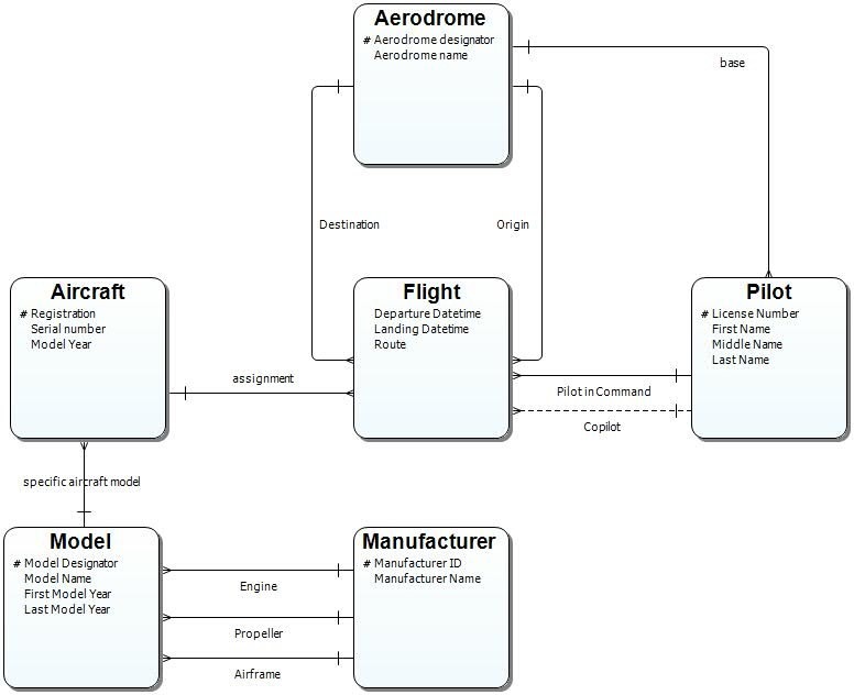
A business analyst created the following conceptual model in ER/Studio Business Architect based on initial requirements.
Logical Model
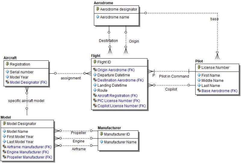
The conceptual model was exported from ER/Studio Business Architect to a logical model in ER/Studio Data Architect. The model and attributes were further elaborated by a data modeler. In the logical model, we chose to display the foreign keys based on the relationships.
Physical Model (Relational)
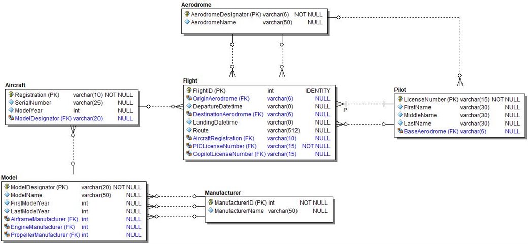
In this case, we decided to implement the database in SQL Server 2016, so we generated the physical model from the logical model within ER/Studio Data Architect. Almost all of the elaboration was completed in the logical model, but we chose to change the physical model display to show data types and NULL properties for the columns.
Alternate Logical
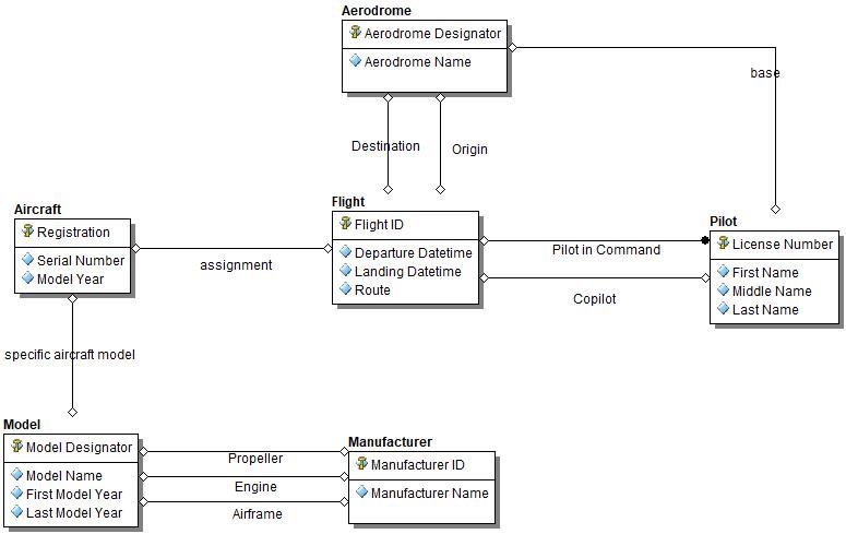
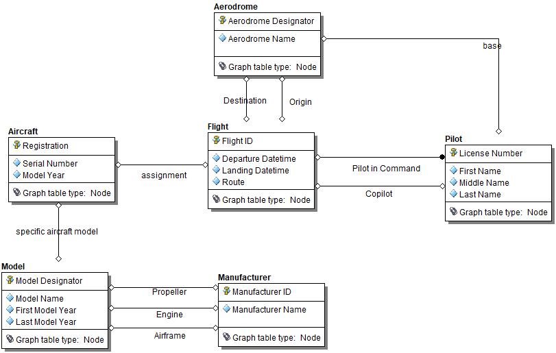
There is a possibility that the business analyst that created the initial conceptual model knew that there were relationships between the entities, but may not have known the cardinality of the relationships at that time. In conceptual modeling, it is not necessary to resolve the model to that degree. The relationships could simply have been created as “non-specific” and if that was the case, the logical model would have been rendered with non-specific relationships as well, as shown below. NOTE: I have also shown this example in IDEF1X notation rather than Information engineering.
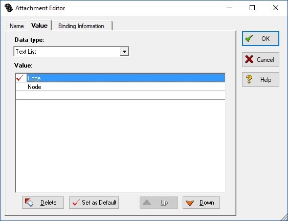
We will now be creating a physical model for a graph database from this. When we create the physical data model for graph, we will need to create an edge tables to represent each of the relationships shown above. I like to document my data models thoroughly, so I want to be able to easily distinguish between Nodes and Edges even in the physical model. Therefore, I have created an attachment (metadata extension) in my data dictionary. I am going to bind this attachment to my entities/tables so I can easily designate which are nodes and which are edges.
Pro tip: I am doing this now because I know that all the existing entities above are nodes. Therefore, I am creating an attachment with 2 values of Edge and Node, with Edge as the default value. When I bind it, I select node for each entity above. When I generate my Edge tables in the next step, I can then bind them to pick up the default value “Edge.”
I have turned on the attachment display property, so I now see the value on each of my entities in the diagram.
Because my relationships are non-specific, I can take advantage of a physical model generation feature in ER/Studio. To generate a physical model, the non-specific relationships must be resolved. Thus, I can have the physical generation create associative entities for each non-specific relationship. That’s exactly what I want. I’ll let the tool do the heavy lifting and then I’ll make some additional modifications to get the model to be exactly what I need.
Now I generate the physical Model and then make a few modifications:
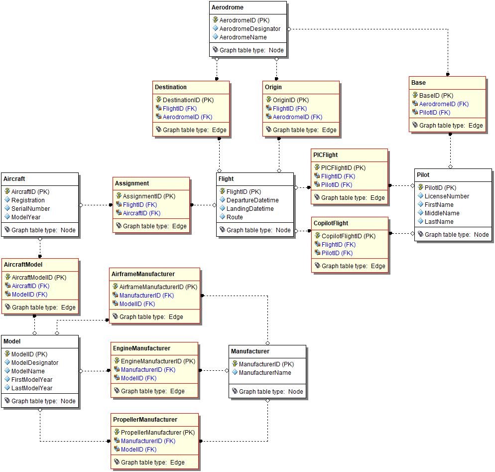
Physical generation has created an associative table for each nonspecific relationship I had in the logical model. Thus 10 Edge tables have been added between the 6 original Nodes.
- I have synchronized the table names of the associations to the relationship names from the logical model
- I have set the value of the Graph Table Type attachment to “Edge” for all the associative tables that were generated
- I have also color coded the associative entities to make them stand out on the diagram
- The edge tables now represent the previous relationships. I have left the connector lines in purely for documentation so it is easier to visually trace which specific nodes a particular edge connects. The generate property has been turned off for all the connectors (since there is no such thing as a referential constraint in a graph data store)
- Each table in the physical model has a synthetic key since this is the practice for nodes and edges in graph data stores.
The resulting model now looks significantly different. We can easily see the nodes and the edges that connect them. Within the edges, the pointers look like foreign keys, so it’s easy to distinguish the pointers from the edge properties.
This example illustrates how it is possible to create a physical model representation for a graph data store. It also illustrates the importance of first modeling the business requirements and business rules using conceptual and logical modeling. It is our chosen deployment platform that has driven the implementation constructs specifically. In the relational database, we preserved a 1:1 correlation between the logical entities and physical tables, while each logical relationship becomes implemented as a constraint. By contrast, the graph implementation replaces each logical relationship with an edge table, while the original entities are represented as node tables. All tables in the graph data store have synthetic keys.
Incidentally, just because we have modeled this as a graph, that doesn’t mean we must deploy it to a graph database. We could actually implement this in a relational database if desired, to familiarize ourselves with how the constructs look when implemented.
Remember – model the business requirements and rules first. Everything else will flow nicely from there, including the choice of multiple physical implementations.
